Introduction
In the realm of digital design and FPGA programming, Verilog Tutorial stands as an essential resource. This tutorial serves as your guide to understanding the intricate world of Verilog HDL, offering a comprehensive journey from its basics to advanced concepts. Whether you're a beginner or seeking to refine your skills, this tutorial will equip you with the knowledge to master Verilog and unleash your creativity in electronic design.
What is Verilog?
Verilog, a Hardware Description Language (HDL), serves as a powerful tool for describing and modeling digital systems and circuits. It is pivotal in digital design and FPGA (Field-Programmable Gate Array) programming. Verilog allows designers to specify the behavior, structure, and functionality of electronic systems at different levels of abstraction.
This language bridges the design process and its physical implementation, enabling engineers to articulate complex digital systems without the need to delve into the intricate details of hardware components. Verilog's syntax is designed to be intuitive and close to traditional programming languages, making it accessible to both hardware and software engineers.
Verilog Code Examples:
module multiplexer_4to1 (
    input wire sel[1:0],
    input wire data[3:0],
    output wire out
);
    assign out = (sel == 2'b00) ? data[0] :
                 (sel == 2'b01) ? data[1] :
                 (sel == 2'b10) ? data[2] :
                                 data[3];
endmodule
The Verilog code provided defines a 4-to-1 multiplexer module named multiplexer_4to1. The module takes two input signals: sel (a 2-bit selection signal) and data (a 4-bit array representing the input data lines). It also has an output signal named out, which represents the selected output data.
The logic inside the module assigns the value of out based on the value of sel:
- If sel is 2'b00, then out will be assigned the value of data[0].
- If sel is 2'b01, then out will be assigned the value of data[1].
- If sel is 2'b10, then out will be assigned the value of data[2].
- Otherwise, if none of the above conditions match (i.e., sel is 2'b11), then out will be assigned the value of data[3].
Verilog Abstraction Levels
Verilog operates across three distinct abstraction levels as a Hardware Description Language (HDL). Each level is vital in the design process, enabling engineers to approach digital design with varying degrees of detail and complexity.
1. Behavioral Level
The behavioral level is the highest abstraction level in Verilog. Here, the focus is primarily on defining the system's functionality and behavior in response to different inputs. It involves creating models using high-level constructs that capture the intended operation of the system. At this stage, designers are concerned with what the system does rather than how it achieves that functionality.
For instance, consider the design of a simple calculator. At the behavioral level, you'd define the calculator's operations (addition, subtraction, etc.) and how it responds to user input without getting into the specific details of how these operations are implemented.
The behavioral level is crucial for system validation, allowing designers to ensure that the system functions as intended before delving into more detailed design stages.
2. Register-Transfer Level (RTL)
As we move closer to the hardware, the RTL abstraction level comes into play. RTL abstraction focuses on the flow of data between registers in the system. It provides a more detailed view of the data path and control logic, capturing the essential elements required for correct system operation.
In the context of the calculator example, at the RTL level, you'd start specifying how the arithmetic operations are carried out using combinations of registers and combinational logic. At this stage, you begin translating the system's behavior into a more hardware-oriented representation.
RTL description is pivotal for understanding the system's data flow and control aspects, forming a critical bridge between the high-level behavior and the actual hardware implementation.
3. Gate Level
The gate-level abstraction is Verilog's lowest and most hardware-centric abstraction level. The design is represented at this level using basic logic gates (AND, OR, NOT, etc.) and flip-flops. This representation reflects the physical implementation of the design, making it suitable for synthesis tools that generate the actual hardware components.
In the case of the calculator, at the gate level, you'd define how each arithmetic operation is implemented using logic gates. This information is crucial for the manufacturing process, as it guides the creation of the physical circuitry.
Gate-level abstraction serves as the foundation for turning a design into a tangible piece of hardware and plays a crucial role in achieving efficient and optimized circuitry.
Verilog Code Examples
1. Behavioral Level Example:
module adder(output reg sum, input reg a, input reg b);
    always @(a or b) begin
        sum = a + b;
    end
endmodule
This Verilog module defines an "adder" module that takes two input signals, a and b, and produces an output signal sum. The always block uses sensitivity to changes in either a or b to perform the addition operation and assign the result to the sum signal.
For example, if you simulate this module and provide inputs a = 3 and b = 5, the output sum would be 8, as 3 + 5 = 8.
The output of the corrected code would be:
If a is 3 and b is 5, then sum would be 8 (3 + 5 = 8).
2. RTL Example
module counter(output reg [3:0] count, input wire clk, input wire reset);
    always @(posedge clk or posedge reset) begin
        if (reset)
            count <= 4'b0000;
        else
            count <= count + 1;
    end
endmodule
This Verilog module defines a simple 4-bit counter that increments its value on every positive clock edge (posedge clk). It also includes a reset mechanism that sets the counter value to 4'b0000 when the reset signal is asserted (posedge reset).
Assuming an initial value of the counter is 4'b0000:
- On the first clock edge (rising edge of clk), the counter will increment to 4'b0001.
- On the second clock edge, it will be 4'b0010.
- On the third clock edge, it will be 4'b0011.
- On the fourth clock edge, it will be 4'b0100.
If the reset signal is asserted, regardless of the clock state, the counter will be set to 4'b0000.
3. Gate Level Example:
module and_gate(output wire out, input wire a, input wire b);
    assign out = a & b;
endmodule
In this Verilog module, an AND gate is implemented using the assign statement. The output results from the logical AND operation between input signals a and b.
The output out will be high (1'b1) only when both input signals a and b are high (1'b1). If any of the input signals are low (1'b0), the output out will be low as well (1'b0).
Here's the logical truth table for the AND gate:
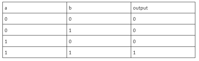
So, the output out will be 1 only when both inputs a and b are 1.
History of Verilog
The history of Verilog traces back to the early 1980s, attributed to Phil Moorby, who conceptualized it as a proprietary language to address the challenges of digital design. Over the years, Verilog evolved from a simple idea into a powerful Hardware Description Language (HDL) that transformed the landscape of digital design and simulation.
Phil Moorby, working at Gateway Design Automation, embarked on the creation of Verilog in the early 1980s. He aimed to develop a language that could accurately describe and simulate digital circuits, simplifying the design process. Verilog was initially designed for modeling and simulation purposes.
In 1990, the first public release of Verilog occurred. This marked a significant milestone as it introduced Verilog to a wider audience of engineers and designers.
Verilog's popularity rapidly surged due to its ability to address real-world design challenges. Its intuitive syntax allowed designers to express intricate designs more effectively. The language's power lies in its capability to model both behavioral and structural aspects of digital systems, enabling comprehensive testing and validation.
- Standardization as IEEE 1364:
A defining moment for Verilog came in 1995 when it was standardized as IEEE 1364, titled "IEEE Standard Hardware Description Language Based on the Verilog Hardware Description Language." This standardization cemented Verilog's position as a robust and widely accepted HDL. It provided a framework for consistent usage, fostering interoperability and consistency across different design tools and platforms.
The standardization of Verilog led to its widespread adoption across the electronics industry. Engineers embraced Verilog as a key tool in digital design, bridging the gap between abstract concepts and tangible hardware. The language's versatility facilitated the development of diverse digital systems, from microprocessors to complex embedded systems.
Verilog's journey didn't stop with standardization. It continued to evolve to meet the demands of emerging technologies and design methodologies. Enhancements and extensions were introduced to cater to new design, verification, and synthesis challenges.
What is Verilog Used For?
Verilog finds its utility across various domains:
- FPGA Development: Verilog is extensively used for programming Field-Programmable Gate Arrays (FPGAs). These devices allow hardware configurations post-manufacturing, making them adaptable for diverse applications.
- ASIC Design: Application-Specific Integrated Circuits (ASICs) are tailor-made for specific functions. Verilog assists in designing ASICs by describing their behavior and structure.
- Digital System Modeling: Verilog enables the creation of accurate models for digital systems before fabrication. This reduces costs and accelerates development.
Verilog vs VHDL
VHDL (VHSIC Hardware Description Language) is another HDL used for similar purposes. While both serve the same purpose, Verilog is often preferred due to its concise syntax and ease of use.
Verilog Simulator
To bring your Verilog designs to life, you need a simulator. Popular choices include ModelSim, Xilinx ISE, and Quartus Prime. These tools allow you to simulate your designs, identify bugs, and verify functionality.
Verilog Documentation
Verilog documentation is crucial for engineers and designers working with the Verilog Hardware Description Language (HDL). It encompasses a range of essential information and resources to effectively utilize Verilog in digital design, simulation, and verification processes. Key aspects of Verilog documentation include:
- Language Specification: Details the syntax, data types, operators, and constructs of Verilog, guiding users on how to declare modules, signals, and hierarchical structures.
- Module and Primitive Reference: Provides information on standard modules and primitives, including built-in components like logic gates and memory elements, helping designers understand their functionality and usage.
- Simulation and Verification: Offers insights into creating testbenches, writing simulation test cases, and performing functional verification, ensuring accurate behavior of designed systems.
- Synthesis Guidelines: Advises on coding practices for efficient hardware synthesis, covering considerations like timing constraints and technology-specific design rules.
- Examples and Tutorials: Offers practical code examples and tutorials to demonstrate Verilog concepts, best practices, and potential pitfalls.
Conclusion
Mastering Verilog opens doors to limitless possibilities in digital design and FPGA programming. The Verilog Syntax abstraction levels and historical significance collectively form a foundation that empowers engineers to create innovative solutions. Verilog remains a cornerstone of modern electronics with real-life applications ranging from FPGA development to ASIC design.
As you embark on your Verilog journey, remember that every line of code you write contributes to shaping the future of digital technology.
FAQs
1. How do I model asynchronous resets in Verilog?
Asynchronous resets can be modeled using an if condition that triggers when the reset signal transitions to a low value (0). This ensures that the reset action occurs independently of the clock signal, helping prevent unintentional glitches.
2. How do I handle floating ("X") or high-impedance ("Z") values in Verilog simulations?
Handling floating or high-impedance values requires conditional checks and assignments. You can use constructs like the ternary operator to specify desired behaviors when dealing with these uncertain or uninitialized states.
3. How do I perform bitwise operations on vectors in Verilog?
Performing bitwise operations on vectors involves using operators like &, |, and ^ to operate on corresponding bits within the vectors. This enables efficient manipulation and processing of data at the bit level.


-d9bdeff6165f4eb1ba2adcebde78e961.svg)


-ae8d039bbd2a41318308f8d26b52ac8f.svg)
-35c169da468a4cc481c6a8505a74826d.webp&w=128&q=75)
-7f4b4f34e09d42bfa73b58f4a230cffa.webp&w=128&q=75)

%20(2)-db0b6f38da9c485faf76e366793c9b9e.webp&w=128&q=75)